Building a Smart RFID Scale for My Filament Spools
Éric WAHL
Full-Stack Developer & Designer
From Software Comfort Zone to Solder Fumes
This project is the direct sequel to Filaventory, my self-hosted filament inventory system. On paper, Filaventory was complete: a Go API, a desktop client, a mobile companion, everything needed to track my growing (concerning?) collection of filament spools.
But there was one step I kept doing by hand: weighing spools and typing the numbers in. And the whole point of the Filaventory API design was that an IoT device could do this for me. Place a spool on a scale, let an RFID reader recognize it, weigh it, push it to the server. Fully automatic.
One small detail: my entire IoT experience consisted of beginner kits and breadboards. No soldering. Ever.
Spoiler alert: the electronics were not the part that broke the most.
The Plan
Before ordering anything, I sketched out what I wanted the final product to look like, pulling from various inspirations I had collected:
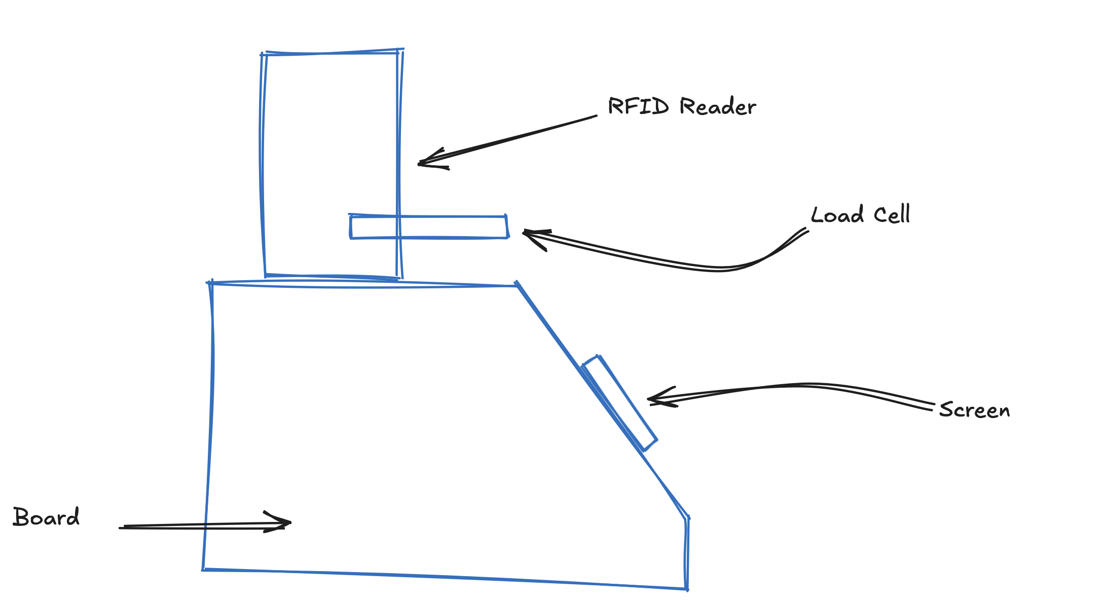
After some research, I landed on this shopping list:
| Component | Specs | Notes |
|---|---|---|
| ESP32 DevKit | 30-pin layout, 4 MB flash | ESP32-WROOM-32 chip |
| RC522 RFID readers | 13.56 MHz NFC, SPI | 2 needed (twin-tag support) |
| HX711 | 24-bit ADC, load cell amplifier | Green PCB modules work fine |
| Load cell | 5 kg or 20 kg | 4-wire half-bridge |
| OLED display | SSD1306 128×64, I²C, 0.96" or 1.3" | I²C address 0x3C |
| KY-040 | Rotary encoder, 360° | The human interface |
First Contact: Breadboard Prototyping
This part felt like home. Wiring components on a breadboard is basically the "hello world" of electronics, and it is exactly what those beginner kits had prepared me for. After some tinkering and a rough 3D printed draft to hold things together, I had a first successful test:
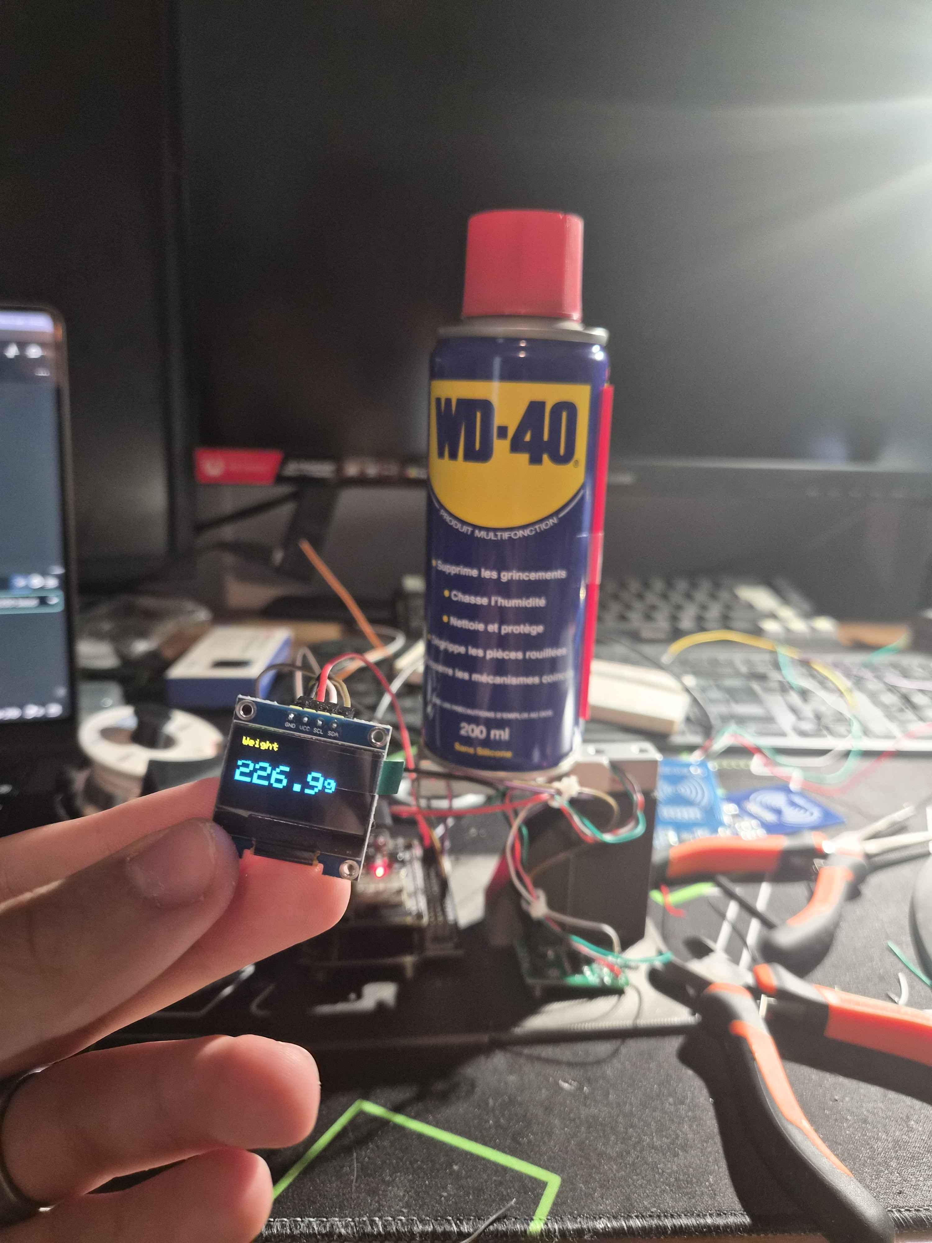
The RFID reader could see a tag, the screen displayed things, the ESP32 talked to my Wi-Fi. Great. Now I just needed to connect the load cell to the HX711 board.
Which requires soldering.
The Soldering Wall
I knew this moment would come. The load cell wires had to be soldered to the HX711 board, and there was no breadboard workaround this time.
So there I was, first soldering iron in hand, no flux, nothing to clean the tip with, and a level of confidence entirely disconnected from my actual skill. I spent around two hours trying to get four soldering points to hold. Four points. Two hours. The tin would ball up, refuse to stick, stick to the iron instead of the pad, every classic beginner mistake, I collected them all.
When the points finally looked "acceptable" (a generous word), I was genuinely scared to touch anything, as if the whole board was held together by hope.
Calibration: A WD40 Can and a Kitchen Scale
With the cell finally connected, I had to calibrate it. The proper way involves certified reference weights. My way involved a can of WD40 and my kitchen scale as the source of truth:
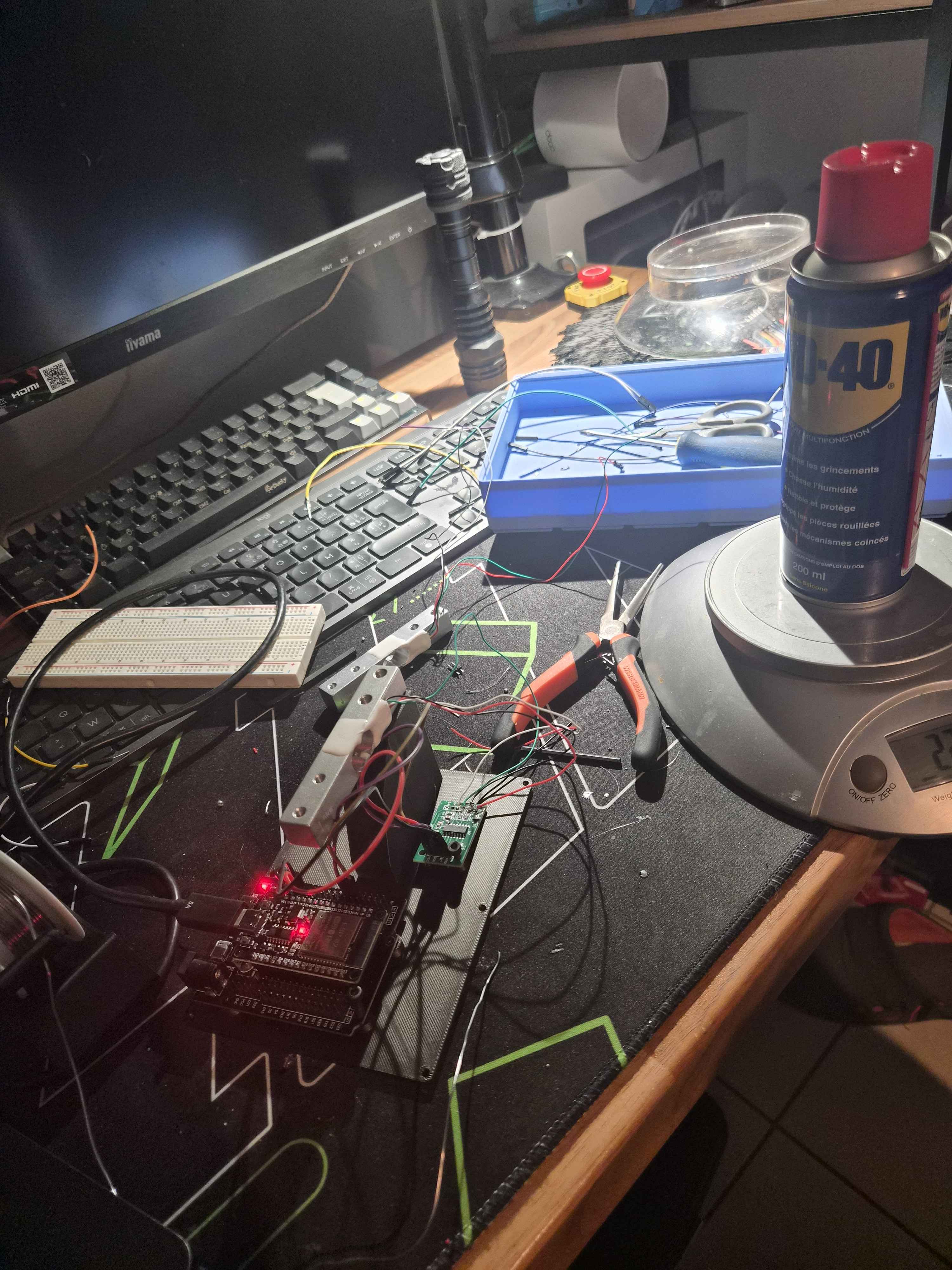
That is when I discovered how sensitive a load cell actually is. Lean on the desk, the value moves. Breathe near it, the value moves. It is honestly impressive, and slightly maddening when you are trying to figure out whether your soldering or your code is the unstable part.
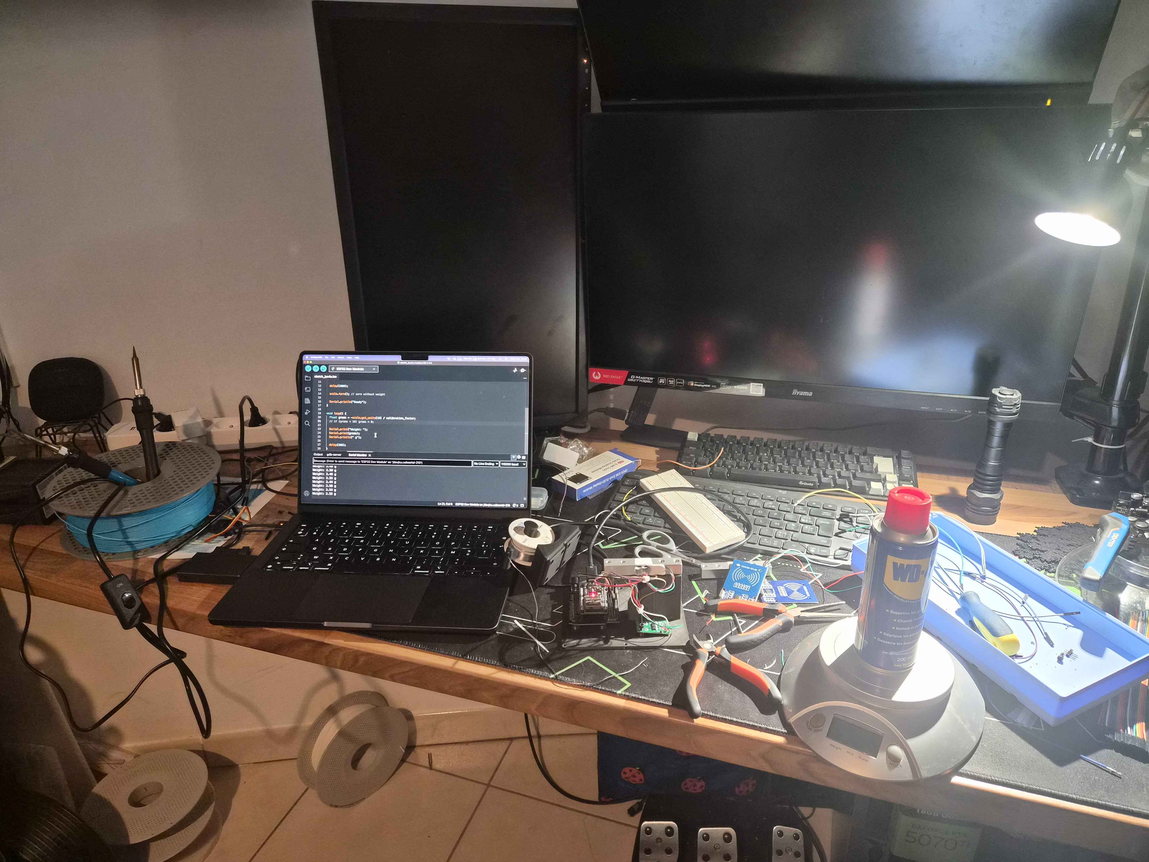
Because yes, that was the recurring theme of the day: writing more and more complete firmware, watching it misbehave, questioning my code, and eventually finding out that a solder joint had let go. Then re-soldering, re-flashing, and repeating. Before I realized it, five hours had evaporated, and my desk was documenting the descent:
The Wiring
For future reference (mine, probably, when I inevitably reopen this thing), here are the full wiring tables:
RC522 RFID Reader #1
| RC522 pin | Function | ESP32 pin |
|---|---|---|
| VCC | 3.3 V | 3V3 |
| GND | Ground | GND |
| SCK | SPI clock | GPIO 18 |
| MOSI | SPI master out | GPIO 23 |
| MISO | SPI master in | GPIO 19 |
| SDA / SS | Chip select | GPIO 5 |
| RST | Reset | GPIO 27 |
| IRQ | (unused) |
RC522 RFID Reader #2
| RC522 pin | Function | ESP32 pin |
|---|---|---|
| VCC | 3.3 V | 3V3 |
| GND | Ground | GND |
| SCK | SPI clock | GPIO 18 (shared) |
| MOSI | SPI master out | GPIO 23 (shared) |
| MISO | SPI master in | GPIO 19 (shared) |
| SDA / SS | Chip select | GPIO 14 (different) |
| RST | Reset | GPIO 25 (different) |
| IRQ | (unused) |
HX711 Load Cell Amplifier
| HX711 pin | Function | ESP32 pin |
|---|---|---|
| VCC | Power | 3V3 (or 5 V if supported) |
| GND | Ground | GND |
| DT (DOUT) | Data out | GPIO 32 |
| SCK | Clock | GPIO 33 |
| E+ | Excitation + | Load cell red wire |
| E− | Excitation − | Load cell black wire |
| A+ | Channel A + | Load cell green or white wire |
| A− | Channel A − | Load cell white or green wire |
OLED Display SSD1306 (I²C)
| OLED pin | Function | ESP32 pin |
|---|---|---|
| VCC | 3.3 V | 3V3 |
| GND | Ground | GND |
| SDA | I²C data | GPIO 21 |
| SCL | I²C clock | GPIO 22 |
Power budget
| Component | Voltage | Typical current | Peak current |
|---|---|---|---|
| ESP32 (idle, Wi-Fi off) | 3.3 V | 50 mA | 80 mA |
| ESP32 (Wi-Fi TX) | 3.3 V | 160 mA | 240 mA |
| RC522 ×2 | 3.3 V | 50 mA each | 200 mA total during read |
| HX711 + load cell | 3.3-5 V | 5 mA | 15 mA |
| OLED | 3.3 V | 15 mA | 25 mA |
| Servo FS90R (idle) | 5 V | 100 mA | |
| Servo FS90R (running) | 5 V | 500 mA | 900 mA (stall) |
| Estimated total | ~750 mA | ~1.5 A |
The full firmware is available in this gist.
A Software Lesson, Learned the Hardware Way
At some point, my OLED display became painfully slow to refresh, and I could not figure out why. The RFID reads were fine, the Wi-Fi was fine, but the interface felt like it was running underwater.
The culprit: the weighing routine. The HX711 read was sitting right in the main loop, blocking everything while it waited for a stable measurement. Every screen refresh, every input, everything was waiting for the scale.
Coming from the software world where I casually spawn async tasks without a second thought, this was a nice slap of humility: on a microcontroller, anything in your loop can block the whole loop. I reworked the code so the weighing process no longer holds everything hostage, and suddenly the display was smooth.
And with that fixed... the whole thing was working!!
Designing the Shell
Time to give this pile of boards and wires a proper body. I measured every board, every mounting hole, planned enough clearance for the cables, and modeled a 3D printed shell in Fusion 360.
While the first draft was printing, an idea crept in: what if the scale had a proper physical interface? A rotary encoder as the main control for local operations: taring the scale, selecting the spool brand to subtract the empty spool weight from the measurement, that kind of thing.
So, back to Fusion 360. I updated the shell with a hole for the encoder, and while I was at it, designed a little bracket shell that would frame the screen and the encoder together. Modeled it, printed everything, started assembling.
I put the screws around the screen shell... and heard a dramatic snap.
The OLED Massacre
Not knowing where the sound came from, I finished mounting the top shell anyway (optimism is a hell of a drug), and of course, the OLED screen was dead.
No problem, they came in a pack of three. Second screen, same assembly, same snap. That is when it clicked: I was overtightening the screws, and instead of snugging the screen against the shell, they were flexing and cracking the glass.
Armed with this knowledge, the third screen would obviously survive. I screwed it in delicately, gently, with the care of someone defusing a bomb. And it worked! But then I noticed a small gap between the screen shell and the scale's top shell. Perfectionism kicked in. One extra quarter-turn of the screwdriver...
Snap.
Three screens. I had killed all three screens.
I ordered another 3-pack, put the project on pause for a day, and took several more days to mourn my lack of delicacy.
Assembly, For Real This Time
When the new screens arrived, I mounted everything correctly (screws barely snug, gap accepted, ego in check), and the scale finally came together:
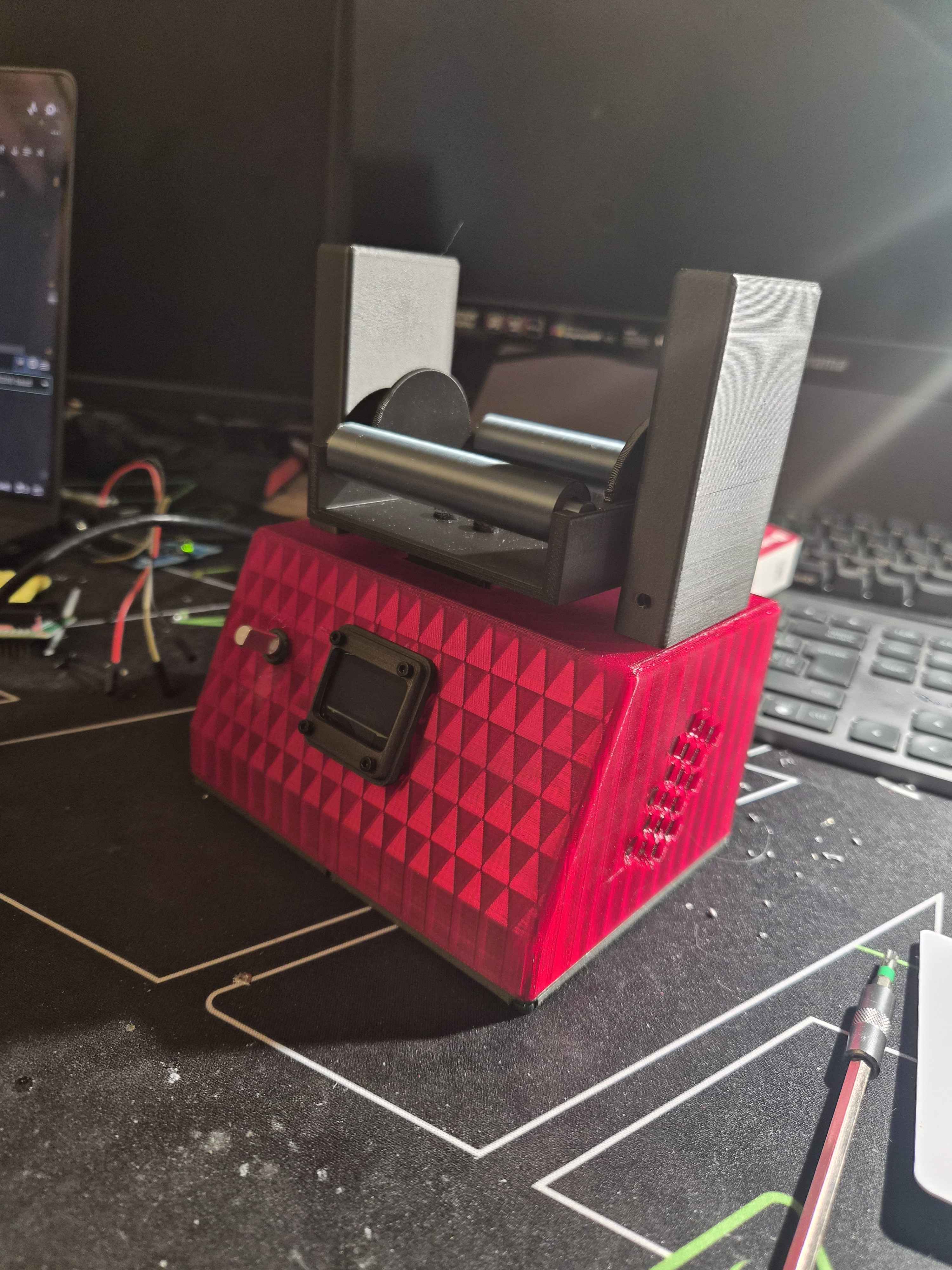
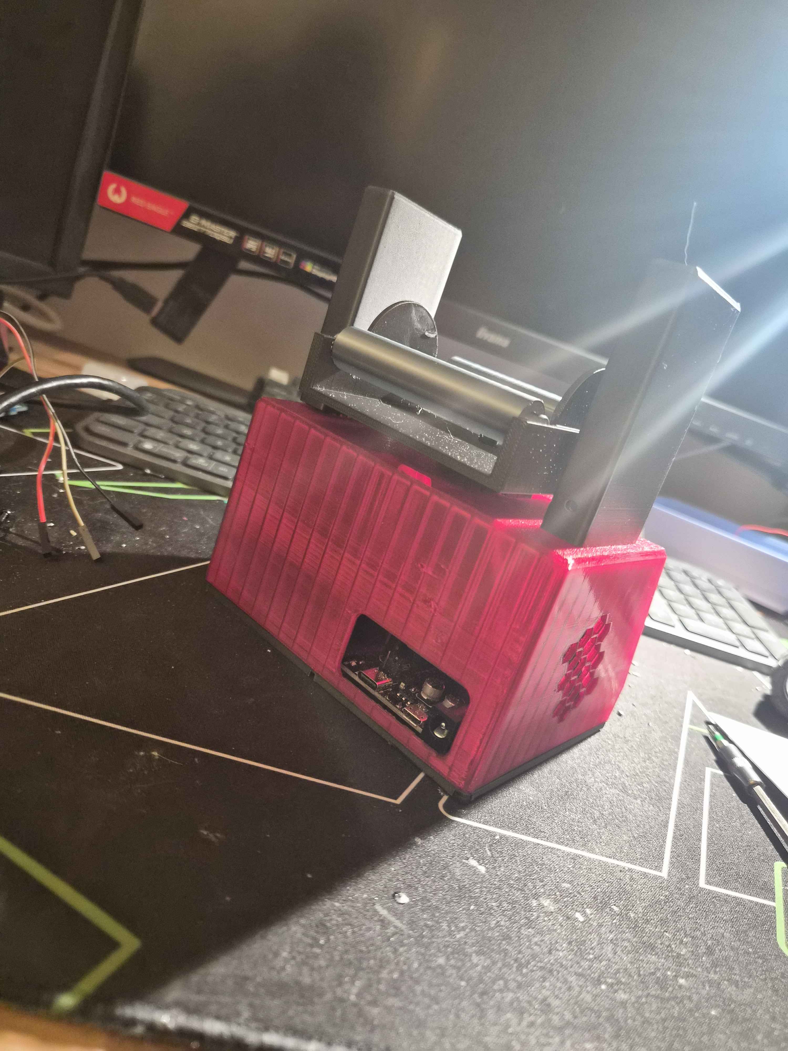
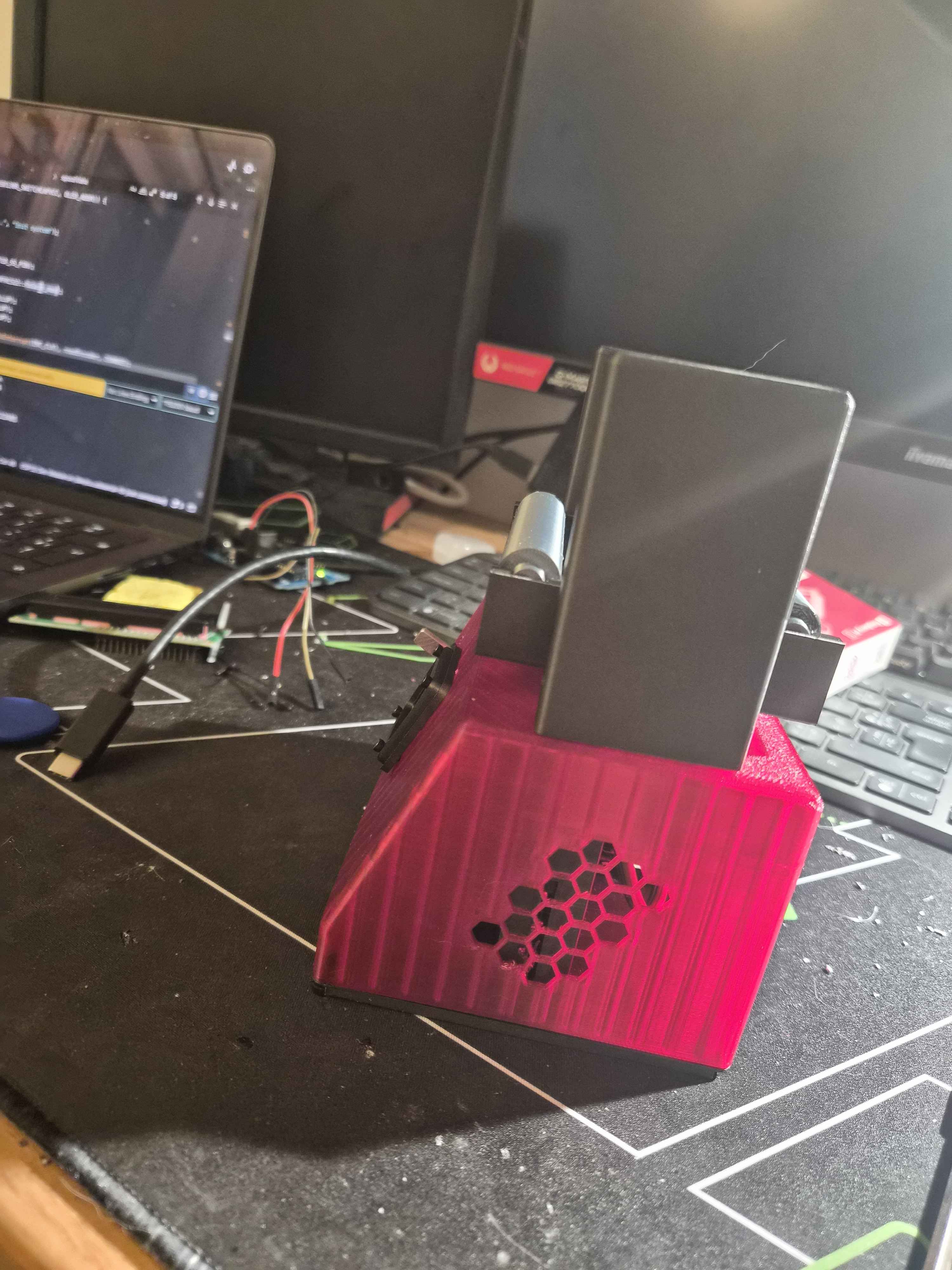
Place a spool on top, the RFID reader identifies it, the load cell weighs it, and the result lands in Filaventory without me typing a single number. The rotary encoder handles the local operations: taring, and selecting the spool profile so the empty spool weight gets subtracted correctly.
What I Take Away From This
What I really want to emphasize with this project is the experience of learning a domain that is genuinely far from my comfort zone. My daily work is software: abstractions, fast iteration loops, undo buttons everywhere. Hardware is patient, physical, and completely indifferent to your confidence level. Every mistake costs real time, real components, and occasionally real OLED screens.
A lot of trial, a lot of error, a lot of learning:
- Soldering is a skill, not a checkbox. Mine is still far from ideal, but it exists now
- Load cells are absurdly sensitive, and calibration with a WD40 can is a legitimate engineering methodology (do not quote me on this)
- On a microcontroller, your loop is sacred; block it and everything suffers
- Screws have a torque limit that is much, much lower than your perfectionism
And at the end of it all, I have a final product that I find as visually pleasing as it is functionally polished. A scale that recognizes my spools, weighs them, and keeps my inventory up to date on its own.
So yes, my solder joints are still not ideal. But I came out of this loaded with knowledge I did not have before, and honestly, that was the whole point.
Have a similar project in mind? Feel free to reach out. I'd love to hear about your hardware adventures, or help troubleshoot if you're stuck in a situation like this.